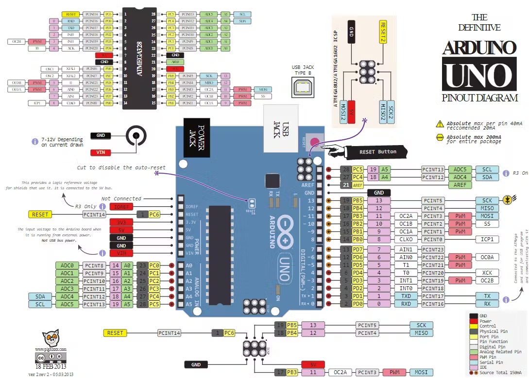
The Arduino Uno is a widely used microcontroller board based on the ATmega328P. It features 14 digital input/output pins, 6 analog inputs, a 16 MHz quartz crystal, a USB connection, a power jack, an ICSP header, and a reset button. Below is a detailed breakdown of all its pins and their functionalities.

1. Power Pins
- Vin (Voltage In): Used to power the board with an external power source (7-12V recommended, 6-20V range).
- 5V: Provides a regulated 5V output for sensors and modules.
- 3.3V: Provides a 3.3V output for low-voltage modules.
- GND (Ground): Ground pins for completing electrical circuits.
- AREF (Analog Reference): Reference voltage for the analog inputs.
- RESET: Resets the microcontroller when pulled LOW.
2. Digital I/O Pins (0-13)
The Arduino Uno has 14 digital input/output (I/O) pins, numbered D0 to D13. They operate at 5V and can provide or receive up to 40mA per pin. Some pins have special functions:
- D0 (RX) & D1 (TX): Serial communication (UART) pins.
- D2 & D3: External Interrupts (INT0, INT1) – Used for interrupt-based functions.
- D3, D5, D6, D9, D10, D11: PWM (Pulse Width Modulation) capable.
- D10, D11, D12, D13: SPI (Serial Peripheral Interface) communication.
- D13: Connected to the built-in LED.
3. Analog Input Pins (A0-A5)
The Arduino Uno has 6 analog input pins, numbered A0 to A5. These pins can read analog signals (0-5V) and convert them into a 10-bit digital value (0-1023).
- A4 (SDA) & A5 (SCL): Used for I2C communication.
4. Communication Pins
Serial Communication (UART)
- D0 (RX): Receive data.
- D1 (TX): Transmit data.
SPI Communication
- D10 (SS): Slave Select.
- D11 (MOSI): Master Out Slave In.
- D12 (MISO): Master In Slave Out.
- D13 (SCK): Serial Clock.
I2C Communication
- A4 (SDA): Serial Data.
- A5 (SCL): Serial Clock.
5. PWM Pins
The Arduino Uno provides 6 PWM-capable digital pins (D3, D5, D6, D9, D10, D11). PWM (Pulse Width Modulation) is used for simulating analog output, such as dimming LEDs or controlling motors.
6. Interrupt Pins
The board supports hardware interrupts on specific digital pins:
- D2 (INT0)
- D3 (INT1)
These can trigger an interrupt routine when a signal change is detected (LOW, RISING, FALLING, or CHANGE).
7. ICSP Header
The ICSP (In-Circuit Serial Programming) header allows programming the ATmega328P directly using an external programmer. It consists of 6 pins:
- MISO, MOSI, SCK, RESET, VCC, GND
8. LED Indicator Pins
- ON LED: Indicates power is supplied to the board.
- L (D13 LED): Built-in LED connected to D13.
- TX LED: Blinks when data is being transmitted over serial.
- RX LED: Blinks when data is being received over serial.
Conclusion
The Arduino Uno pinout is versatile and well-suited for beginners and professionals. Understanding its pins helps in utilizing the board efficiently for various projects, including IoT, robotics, and automation.
Would you like to add diagrams or pinout images to enhance the guide?