If you’ve ever used a volume knob, a scrolling wheel, or a menu navigation system, you’ve likely interacted with a rotary encoder. In this tutorial, we will explore how to use the KY-040 rotary encoder with an Arduino to detect rotation direction and button presses. You’ll learn how to wire the encoder, write the code, and test it to control your projects more efficiently.
What is a Rotary Encoder?
A rotary encoder is an electromechanical device that converts rotational motion into a digital signal. These encoders are commonly used in devices like volume knobs, menu selectors, and motor control systems. The KY-040 rotary encoder has three main pins to interact with:
- CLK (Clock Pin): Sends pulses when the encoder is rotated.
- DT (Data Pin): Determines the direction of rotation.
- SW (Switch Pin): Detects button presses.
- VCC & GND: Power supply connections.
Components Needed
Here’s a list of the components required for this project:
- 1 x Arduino Uno/Nano/Mega
- 1 x Rotary Encoder (KY-040)
- Jumper Wires
Wiring the Rotary Encoder
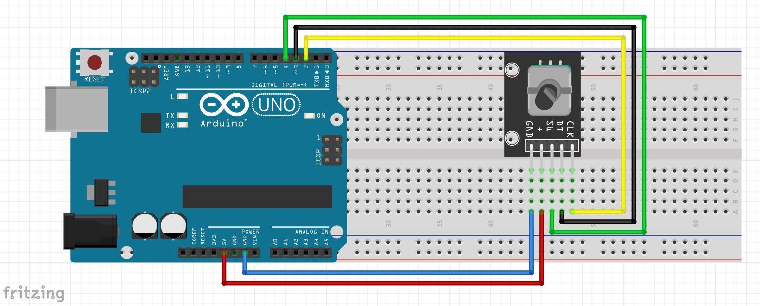
Below is the wiring diagram for connecting the KY-040 rotary encoder to your Arduino. It’s a simple setup:
- CLK (Clock) → Pin D2
- DT (Data) → Pin D3
- SW (Switch) → Pin D4
- VCC → 5V Pin
- GND → GND Pin
Schematic Diagram
Here’s the schematic that visually shows how to wire the rotary encoder to the Arduino:
(Replace with your image URL)
Arduino Code
Now, let’s take a look at the code to get the rotary encoder working with your Arduino. This code will detect the rotation direction (clockwise or counterclockwise) and the button press.
Here Is Github Link For Code
https://github.com/ElectroIoT/37-in-1-Sensors-Kit-Code-And-Libraries/tree/main/15.Rotary_Encoder_Module
All In One 37-1 Sensor
https://github.com/ElectroIoT/37-in-1-Sensors-Kit-Code-And-Libraries
How It Works
- Detecting Rotation Direction:
- If the DT pin reads HIGH before the CLK pin, the encoder is rotating clockwise.
- If the CLK pin reads HIGH before the DT pin, the encoder is rotating counterclockwise.
- Button Press Detection:
The button integrated into the encoder will trigger a “Button Pressed” message when it’s pressed.
Testing the Rotary Encoder
Follow these steps to test the rotary encoder:
- Wiring: Connect the encoder to your Arduino as shown above.
- Upload the Code: Open the Arduino IDE, copy the provided code, and upload it to your Arduino.
- Open the Serial Monitor: Go to Tools > Serial Monitor in the Arduino IDE to see the output.
- Rotate the Encoder: Rotate the encoder clockwise and counterclockwise, and observe the direction printed on the Serial Monitor.
- Press the Button: Press the encoder’s switch and see the “Button Pressed” message appear.
Applications of Rotary Encoders
Rotary encoders are versatile and have numerous applications:
- Volume control in audio systems.
- Menu navigation in devices like 3D printers and CNC machines.
- Motor speed control in robotics or automation.
- Detection of movement and position in robotics and other precision machines.
Conclusion
In this tutorial, we’ve learned how to wire and program a rotary encoder to interface with an Arduino. We covered how to detect rotation direction and button presses, allowing you to incorporate this useful component into your projects.
Connect with Me
Feel free to connect with me and check out more of my work: