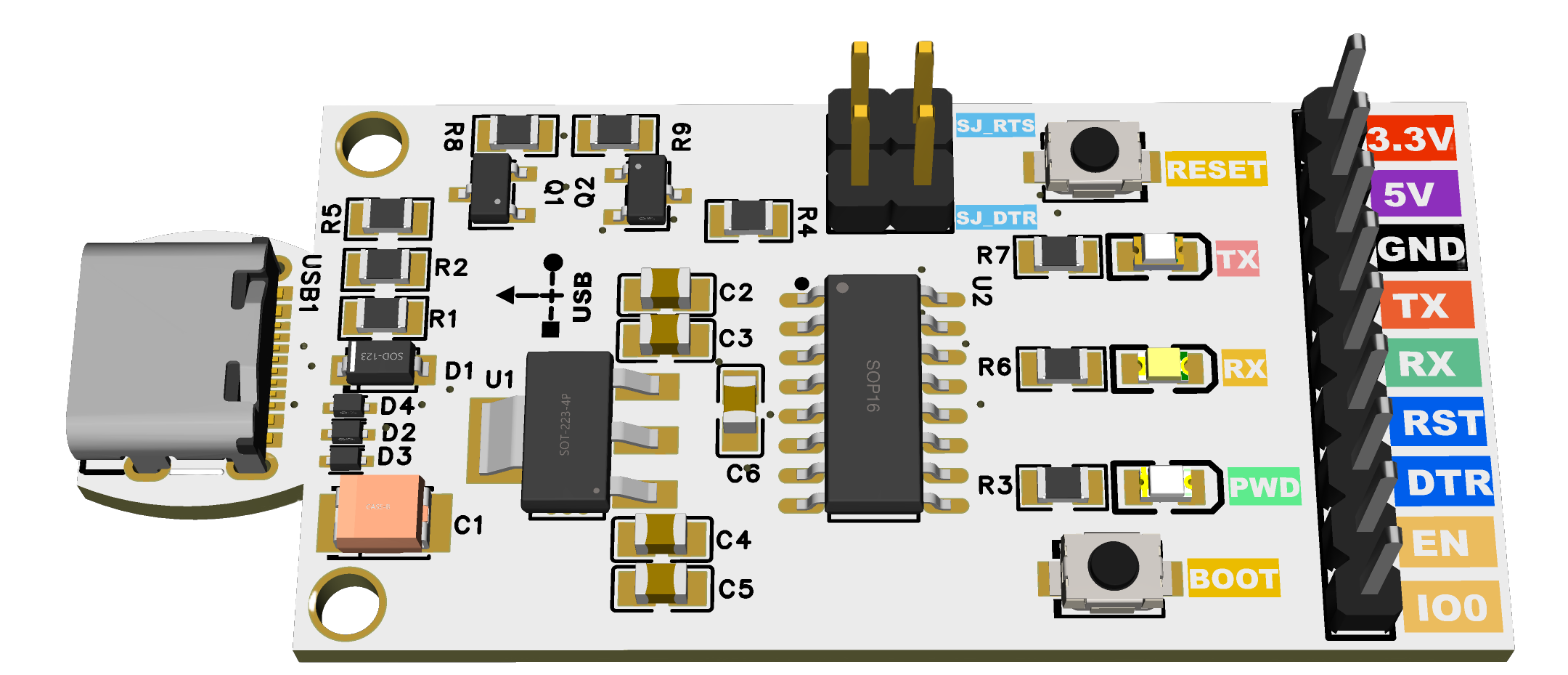

Final 3D PCB Render with Color-Coded Silkscreen 
Final 3D PCB Render with Color-Coded Silkscreen
This project is a universal USB-to-Serial flasher board based on the CH340C USB-UART bridge.
It is designed for ESP8266, ESP32, ESP01, Arduino, and other microcontrollers with UART bootloading.
Unlike cheap USB-to-TTL adapters, this flasher includes:
- Auto-programming circuit (RTS/DTR → EN/IO0)
- Reset & Boot pushbuttons for manual control
- Colored silkscreen pin labels for easy connection
- Status LEDs (PWR, TX, RX)
- USB-C connector with ESD protection
- Clean PCB layout with ground pours
This makes it a reliable, beginner-friendly, and professional-quality programmer.
- 🔌 USB-C connector (reversible, modern interface)
- ⚡ CH340C USB-UART chip (stable drivers, Windows/Linux/macOS support)
- 🔒 ESD protection diodes on USB D+/D−
- 🔄 Auto-reset circuit for ESP32/ESP8266 (no need to hold BOOT manually)
- ⏹ Manual RESET & BOOT buttons for recovery and testing
- 🌈 Color-coded silkscreen pin labels for easy wiring:
- 3.3V (Red), 5V (Purple), GND (Black), TX (Orange), RX (Green), RST/DTR (Blue), EN/IO0 (Yellow)
- 💡 LED indicators:
- Green = Power
- Orange = TX activity
- Yellow = RX activity
- 🛡️ SJ jumpers (SJ_RTS, SJ_DTR) to enable/disable auto-programming
- 📏 Compact PCB: ~62 × 27 mm
| Pin | Function | Color |
|---|---|---|
| 3.3V | 3.3 V output | 🔴 Red |
| 5V | 5 V from USB | 🟣 Purple |
| GND | Ground | ⚫ Black |
| TX | UART Transmit | 🟧 Orange |
| RX | UART Receive | 🟩 Green |
| RST | Reset / EN | 🟦 Blue |
| DTR | Data Terminal Ready | 🟦 Blue |
| EN | Chip Enable | 🟨 Yellow |
| IO0 | Boot Mode Select | 🟨 Yellow |
Two solder jumpers are included:
- SJ_RTS → Connects RTS → EN (reset line).
- SJ_DTR → Connects DTR → IO0 (boot line).
- Default = closed (auto-programming works normally).
- If you cut the jumper, auto-reset for that pin is disabled.
- This lets you take manual control via the pushbutton, useful for debugging or when using the board as a generic USB-UART adapter.
👉 For ESP32/ESP8266 flashing: leave both SJ closed.
👉 For Arduino or other MCUs without auto-program support: you can cut them.
Here are the key components (from your BOM):
| Qty | Reference | Value | Part No / Notes |
|---|---|---|---|
| 1 | U2 | CH340C | USB-UART bridge |
| 1 | U1 | SGM2212-3.3 | 3.3V LDO regulator |
| 2 | Q1, Q2 | MMBT3904 | NPN for auto-program |
| 2 | R8, R9 | 100k | Base pulldown resistors |
| 2 | R1, R2 | 10k | Base resistors (RTS/DTR) |
| 2 | R4, R5 | 10k | Pull-ups (EN, IO0) |
| 1 | R3 | 1k | Power LED resistor |
| 2 | R6, R7 | 2.2k | TX/RX LED resistors |
| 3 | LED1-3 | Green/Orange/Yellow | Power, TX, RX indicators |
| 3 | D2–D4 | LESD5D5.0 | USB ESD protection |
| 1 | D1 | 1N5819 | Reverse protection |
| 5 | C1–C5 | 10 µF | Bulk capacitors |
| 3 | C3, C5, C6 | 100 nF | Decoupling capacitors |
| 2 | SW1, SW2 | Reset/Boot buttons | Tactile SMD |
| 1 | USB1 | USB-C connector | Receptacle |
(📑 Full detailed BOM available in Excel file)

Final routed PCB layout with ground pours

Final routed PCB Schematic
- Connect the board via USB-C to your PC.
- Install CH340 drivers (Windows only, Linux/macOS usually auto-detect).
- Connect your target microcontroller using the 9-pin header.
- ESP32/ESP8266: connect 3.3V, GND, TX, RX, EN, IO0.
- Arduino: connect VCC, GND, TX, RX, RST.
- Flashing ESP8266/ESP32:
- Auto-programming works (no need to hold BOOT).
- Use Arduino IDE / esptool.py / PlatformIO to upload code.
- Flashing Arduino/AVR:
- Connect TX/RX + RST.
- Disable SJ jumpers if needed.
- Manual boot mode:
- Hold BOOT + press RESET → release RESET, then release BOOT.
- LEDs:
- PWR = board powered
- TX = blinks when sending data
- RX = blinks when receiving data
- 🟢 Safer for ESP (3.3V regulated output, correct auto-programming circuit).
- 🟢 Beginner-friendly (color-coded silkscreen, clear pinout).
- 🟢 Robust USB-C connector with ESD protection.
- 🟢 Supports multiple targets: ESP32, ESP8266, ESP01, Arduino, STM32 (UART bootloader).
- 🟢 Debug-friendly: RESET/BOOT buttons, jumpers to disable auto-reset.
- ✅ 3D Render (top view)
- ✅ PCB Layout (routing + pours)
- ✅ BOM (Excel, LCSC parts)
- ✅ Schematics (EasyEDA / PDF)
All files can be published on GitHub/PCBWay for sharing.
👨💻 Designed by ElectroIoT
🔗 Website: https://electroiot.in
▶️ YouTube: ElectroIoT-IN
📸 Instagram: @electroiot_in
📧 Email: electroiot.in@gmail.com
✨ Open Source Hardware for Makers – Share, Learn & Build Together!
You’ve distilled a complex topic into something very manageable.