Welcome to another exciting DIY project! In this post, I’ll walk you through the design and features of my custom-built ESP32-C3-based 8-Channel Relay Board — a powerful and flexible controller for your smart home automation needs.
🔧 Project Overview
This board is built around the ESP32-C3 SuperMini, offering Wi-Fi control for up to 8 electrical appliances like lights, fans, pumps, or sockets. It’s designed for seamless integration with Home Assistant, Tasmota, ESPHome, or custom Arduino firmware.
With onboard AC-DC power conversion, relay drivers, I2C expansion headers, and extra GPIOs, this is a ready-to-use smart switchboard — ideal for both hobbyists and smart home enthusiasts.
✅ Key Features
-
🧠 Microcontroller: ESP32-C3 SuperMini (Wi-Fi + BLE)
-
🔌 Relay Outputs: 8x channels (10A @ 250V AC each)
-
💡 Relay Driver: ULN2803A
-
⚡ Power Input: 100–240V AC (HLK-PM01 module)
-
🔋 Onboard Power Regulation: 5V and 3.3V (via LM2596)
-
🔄 I2C Expansion: Connect OLED, DHT, BMP, etc.
-
🔗 GPIO Expansion: 3 extra digital pins available
-
🏠 Firmware Support: ESPHome, Tasmota, Arduino IDE
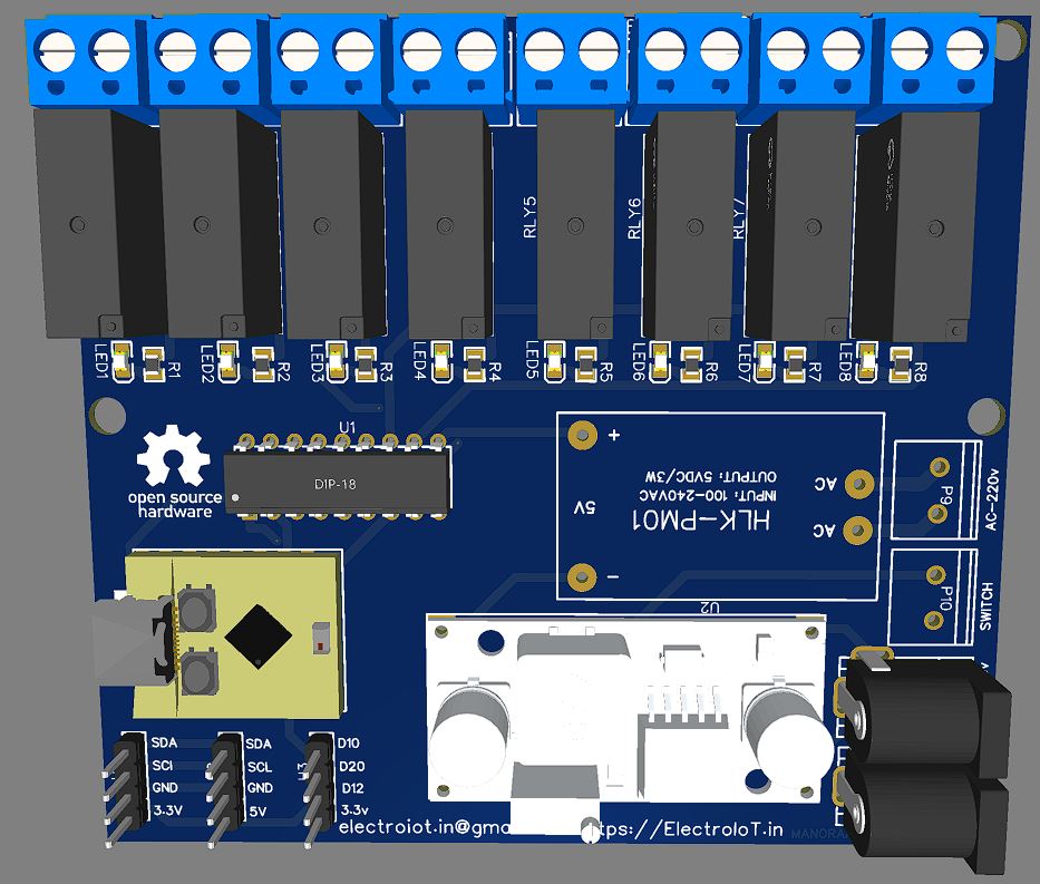
🖼️ PCB Preview
(Insert 3D PCB Image, PCB Layout Image, Schematic Image)
The board was designed using EasyEDA and follows proper layout practices with AC-DC isolation, wide power traces, labeled pins, and a compact silkscreen.
⚙️ How It Works
-
ESP32-C3 controls each relay through GPIOs.
-
ULN2803A handles high-current relay switching.
-
Relays receive 5V DC power from onboard HLK-PM01.
-
ESP32-C3 is powered with regulated 3.3V via LM2596.
-
Extra headers allow connection of sensors or displays (I2C).
-
Works with Home Assistant, voice assistants, or custom code.
📦 Components Used
| Component | Quantity |
|---|---|
| ESP32-C3 SuperMini | 1 |
| 5V Relay (10A) | 8 |
| ULN2803A | 1 |
| HLK-PM01 (AC to 5V) | 1 |
| LM2596 Buck Converter | 1 |
| LEDs + Resistors | 8 |
| Screw Terminals | 8 |
| Push Button | 1 |
| Custom PCB | 1 |
🔌 Firmware Options
🏠 ESPHome (for Home Assistant)
💻 Arduino IDE Example
Use digitalWrite() on GPIO0 to GPIO7 to control relays.
🌐 Tasmota Template
🛠️ Use Cases
-
Control room lights, fans, and plugs over Wi-Fi
-
Schedule-based automation via Home Assistant
-
Add DHT11 or OLED for temperature display
-
Create voice-controlled switches (Alexa, Google Assistant)
-
Monitor status on your phone or dashboard
📁 Downloads
-
✅ Gerber files
-
✅ Schematic PDF
-
✅ BOM (Bill of Materials)
-
✅ ESPHome YAML example
-
✅ Arduino sketch (Coming soon)
📣 Final Thoughts
This ESP32-C3 relay board is a powerful, clean, and modular solution for home automation. Whether you’re building your first smart controller or upgrading your existing setup, this board gives you full control, expansion flexibility, and firmware freedom.
📬 Contact & Credits
-
🔗 Website: https://electroiot.in
-
✉️ Email: electroiot.in@gmail.com
-
📸 Gerber and source files available on: PCBWay Project Page (insert link)
-
💡 Design by: Manoranjan Das
GITHUB
https://github.com/ElectroIoT/8ch-ESP32-c3-Relay-Module
Very good site you have here but I was curious if you knew of any message boards that cover the same topics talked about here?
I’d really like to be a part of community where I
can get feed-back from other knowledgeable people that share the same interest.
If you have any suggestions, please let me know.
Thanks a lot!
Hi, i am interested in your ESP32-C3 and 8-Channel Relay with customization. Please reach me on +91 9791567776.